In my quest to build an electric scooter from the ground up, the first step is to build a speed controller for the motor. Given that brushless DC motors (BLDC) are readily available in hobby shops, are high efficiency, and relatively inexpensive, the plan is to build a controller for a BLDC motor.
The brushless DC motor is a high-efficiency motor which uses permanent magnets on the rotor, and electromagnets on the stator to control the rotation of the rotor. The rotor and stator are only attached via bearings which support the rotor as it spins; the small contact area allows for the high efficiency of the motor.
In order to make the rotor spin in a desired direction, the electromagnets must be activated in a certain order to attract the magnets on the rotor to the electromagnets on the stator. This magnetic attraction is what causes the rotor to spin, and the sequence of steps is called the commutation sequence.
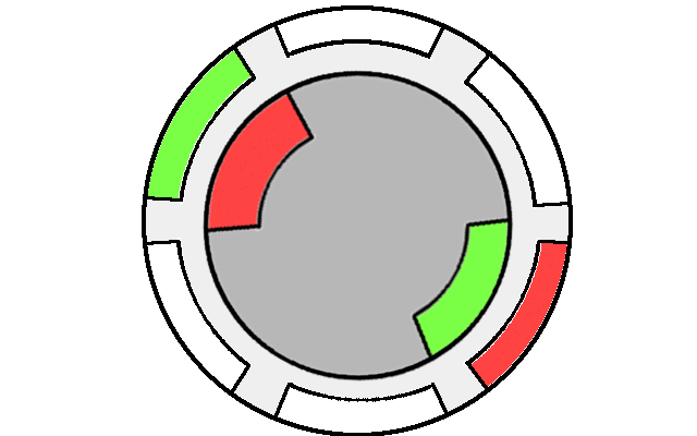
In the animation above. you can see that as the stators are energized in order, the rotor “chases” the magnetic fields. This is the basic commutation sequence for BLDC motors.
In order to maximize torque on the rotor, the field applied by the stator should be at an angle of 90 degrees to the orientation of the rotor. The relationship between torque \(\tau\), magnetic moment \(m\) of the rotor, and the field supplied by the stator \(B\) is
\[\tau = m \times B\]The cross product is at is greatest when the vectors are at right angles to each other. The control algorithm used to try to maintain the 90 degree separation is called field-oriented control (FOC).
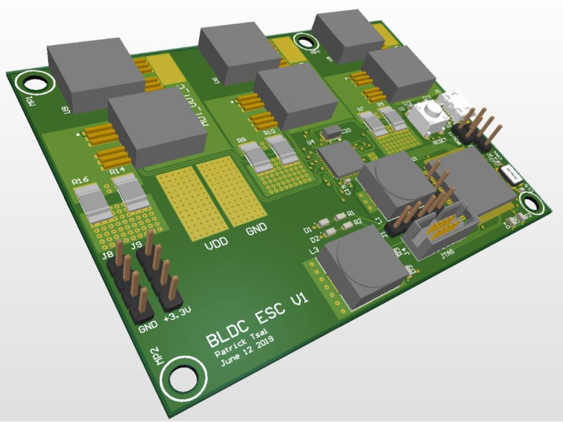
PCB Design
Common battery packs for hobby electronics don’t usually exceed 60V, so the main parts I chose were:
- IRFS7530 MOSFETs for its 60V \(V_{DS}\), low \(R_{DS}\) for minimal power dissipation, and high continuous and pulsed current capability (240A and 1000A+, respectively)
- DRV8353RS triple half-bridge driver to drive the MOSFETs; it’s an all in one package that can be programmed by a microcontroller via SPI, has a built-in hardware-configurable buck converter that can convert the high battery voltage to a lower voltage to power other stuff like microprocessors, and has current sense amplifiers on all three phases
- STM32F407 microcontroller; it has plenty of compute power and peripherals, and a lot of community support. Documentation is all over the place but the chips are very good in my opinion (disclaimer, I am a STM shareholder).
There are six MOSFETs arranged in three half-bridges, one for each phase of the three-phase BLDC. Each half-bridge has a current sense resistor on the low-side. The max amperage of the IRFS7530 is insanely high, 240A, so it’s likely that temperature increase on the PCB, MOSFETs, or the sense resistors will be the limiting factor in current capacity. Besides possibly adding heatsinks to the MOSFETs and/or PCBs, it is essential that high-amperage traces on the PCB be wide enough to reduce resistance and heating, and all wires soldered to the motor/battery need to be thick enough to handle all the current.
To accomplish that, I put huge copper pours on the top/bottom layers and stitched them together with vias; together with the internal planes, both VDD and GND have three large traces to go through. I also removed thermal reliefs on all vias and pads on the MOSFETs and sense resistors which should help with reducing resistance, but made soldering those components difficult.
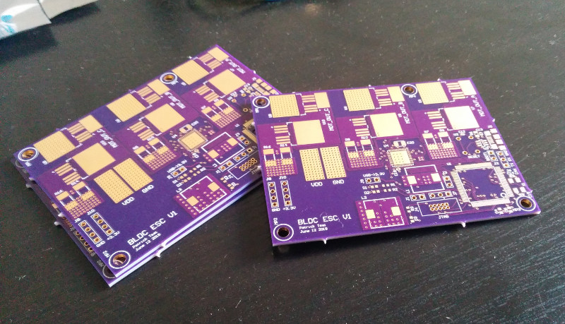
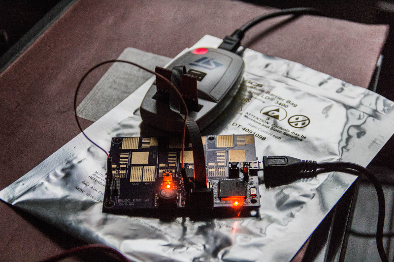
I got the boards made through OSHPark, and after soldering a minimal amount of components to a board and debugging it for a while, I finally got LEDs to blink.
More coming soon…
last updated June 29, 2020
Update Sept. 2020
I decided to make my bike electric instead of making a separate electric scooter, so I bought a 48V front wheel motor for my bike. While testing the ESC with the motor, the DRV8353 appears to have blown up internally somehow, as the idle current is now 0.13A at 15V instead of the ~0.01A as usual - the chip is super hot by touch so the energy is probably going to a short somewhere. I’m not totally surprised it died, given how many reports I read on the Internet of DRV chips dying during usage - just search “DRV blew up” and you’ll see.
My power supply is cheap so it may have been a voltage pulse on VDD that killed the DRV8353, but the supply was only set at 15V. I’m not seeing too many other possibilities for failure, but next version I’ll have clamping diodes on everything.